-
Star flexible coupling
-
Plum-shaped elastic coupling
-
Slider coupling
-
Diaphragm coupling
-
Elastic sleeve pin coupling
-
Elastic pin coupling
-
Elastic pin gear coupling
-
Drum gear coupling
-
Rigid coupling
-
Tyre coupling
-
Universal coupling
-
Water pump coupling
-
Roller chain coupling
-
Reducer bracket
-
Blender
-
Stuffing box
-
Expansion sleeve
-
Various coupling accessories
-
Product Navigation
- LM type basic plum blossom elastic coupling
- LT type (formerly TL type) elastic sleeve pin coupling
- LMD (formerly MLZ) type single flange plum-shaped bullet
- XL type star elastic coupling
- Ever-Power Factory Slider Coupling
- Ever-Power explains the elastic pin teeth for you
- Operation and structure of star coupling
- The editor will introduce you to each model
- The coupling is divided into lubricated and non-lubricated
- What to consider when buying a coupling
-
更新 更新
-
Product display Coupling > Product center > Rigid coupling >
Flange coupling
时间:2013-08-01 17:58 作者:admin 点击:
次

Flange coupling detailed parameters
Flange coupling is a rigid coupling. It connects two flanged half couplings to the two shafts with ordinary flat keys, and then connects the two half couplings into one body with bolts to transmit motion And torque.
Flange couplings have high requirements for the neutrality of the two shafts. When there is relative displacement between the two shafts, additional loads will be caused in the machine parts and the working conditions will deteriorate. This is its main shortcoming, but due to the structure It is simple, low cost, and can transmit large torque, so when the speed is low, there is no impact, and the rigidity of the shaft is large.The material of the flange coupling can be gray cast iron or carbon steel, and cast steel or forged steel should be used for heavy loads or when the peripheral speed is greater than 30 m/s.Flange couplings have high requirements on the neutrality of the two shafts. When the two shafts have relative displacement, they will cause additional loads in the machine parts and worsen the working conditions. This is its main disadvantage.However, due to its simple structure, low cost, and large torque transmission, it is often used when the speed is low, there is no impact, the shaft is rigid, and the neutrality is good.
There are two main structural forms of flange couplings:
1. Rely on the reamed hole and use the bolt to realize the two-axis centering and rely on the bolt rod to bear the extrusion and shear to transmit the torque;
2. It is centered by matching the convex shoulder on one half coupling with the groove on the other half coupling.
The bolts connecting the two half-couplings can be ordinary bolts of grade A and B, and the torque is transmitted by the frictional moment of the joint surface of the two half-couplings.
The material of the flange coupling can be gray cast iron or carbon steel, and cast steel or forged steel should be used under heavy load or when the peripheral speed is greater than 30 m/s.
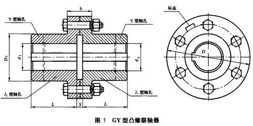
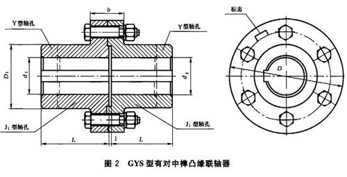
Basic parameters and main dimensions of GY, GYS, GYH flange couplings (GB/T 5843-2003) (Unit: mm)
| model | Nominal torque Tn(Nm) | Allowable speed [n]r/min | Diameter of shaft hole | Length of shaft hole | D | b | b1 | S | Moment of inertia Kg.m2 | Mass kg | |
| d1 d2 | Y type | J1 type | |||||||||
|
GY1 GYS1 GYH1 |
25 | 12000 | 12,14 | 32 | 27 | 80 | 26 | 42 | 6 | 0.0008 | 1.16 |
| 16,18,19 | 42 | 30 | |||||||||
|
GY2 GYS2 GYH2 |
63 | 1000 | 16,18,19 | 42 | 30 | 90 | 28 | 44 | 6 | 0.0015 | 1.72 |
| 20,22,24 | 52 | 38 | |||||||||
| 25 | 62 | 44 | |||||||||
|
GY3 GYS3 GYH3 |
112 | 9500 | 20,22,24 | 52 | 38 | 100 | 30 | 46 | 6 | 0.0025 | 2.38 |
| 62 | 44 | ||||||||||
| 25,28 | |||||||||||
|
GY4 GYS4 GYH4 |
224 | 9000 | 25,28 | 62 | 44 | 105 | 32 | 48 | 6 | 0.003 | 3.15 |
| 30,32,35 | 82 | 60 | |||||||||
|
GY5 GYS5 GYH5 |
400 | 8000 | 30,32,35,38 | 82 | 60 | 120 | 36 | 52 | 8 | 0.007 | 5.43 |
| 40,42 | 112 | 84 | |||||||||
|
GY6 GYS6 GYH6 |
900 | 6800 | 38 | 82 | 60 | 140 | 40 | 56 | 8 | 0.015 | 7.59 |
| 40,42,45,48,50 | 112 | 84 | |||||||||
|
GY7 GYS7 GYH7 |
1600 | 6000 | 48,50,55,56 | 112 | 84 | 160 | 40 | 56 | 8 | 0.031 | 13.1 |
| 60,63 | 142 | 107 | |||||||||
|
GY8 GYS8 GYH8 |
3150 | 4800 | 60,63,65,70,71,75 | 142 | 107 | 200 | 50 | 68 | 10 | 0.103 | 27.5 |
| 80 | 172 | 132 | |||||||||
|
GY9 GYS9 GYH9 |
6300 | 3600 | 75 | 142 | 107 | 260 | 66 | 84 | 10 | 0.319 | 47.8 |
| 80,85,90,95 | 172 | 132 | |||||||||
| 100 | 212 | 167 | |||||||||
|
GY10 GYS10 GYH10 |
10000 | 3200 | 90,95 | 172 | 132 | 300 | 72 | 90 | 10 | 0.720 | 82.0 |
| 100,110,120,125 | 212 | 167 | |||||||||
|
GY11 GYS11 GYH11 |
25000 | 2500 | 120,125 | 212 | 167 | 380 | 80 | 98 | 10 | 2.278 | 162.2 |
| 130,140,150 | 252 | 202 | |||||||||
| 160 | 302 | 242 | |||||||||
|
GY12 GYS12 GYH12 |
50000 | 2000 | 150 | 252 | 202 | 460 | 92 | 112 | 12 | 5.923 | 285.6 |
| 160,170,180 | 302 | 242 | |||||||||
| 190,200 | 352 | 282 | |||||||||
|
GY13 GYS13 GYH13 |
100000 | 1600 | 190,200,220 | 352 | 282 | 590 | 110 | 130 | 12 | 19.978 | 611.9 |
| 240,250 | |||||||||||
| 410 | 330 | ||||||||||
Note: The mass and moment of inertia are calculated based on the Y/J1 shaft hole combination of the GY coupling and the minimum shaft hole diameter
You may be right | Rigid coupling | JQ type clamp coupling | Interested in other products
- LM type basic plum blossom elastic coupling LT type (formerly TL type) elastic sleeve pin coupling LMD (formerly MLZ) type single flange plum-shaped bullet XL type star elastic coupling T type plum blossom hexagonal water pump counter wheel pad
-
Popular products