-
Star flexible coupling
-
Plum-shaped elastic coupling
-
Slider coupling
-
Diaphragm coupling
-
Elastic sleeve pin coupling
-
Elastic pin coupling
-
Elastic pin gear coupling
-
Drum gear coupling
-
Rigid coupling
-
Tyre coupling
-
Universal coupling
-
Water pump coupling
-
Roller chain coupling
-
Reducer bracket
-
Blender
-
Stuffing box
-
Expansion sleeve
-
Various coupling accessories
-
Product Navigation
- LM type basic plum blossom elastic coupling
- LT type (formerly TL type) elastic sleeve pin coupling
- LMD (formerly MLZ) type single flange plum-shaped bullet
- XL type star elastic coupling
- Ever-Power Factory Slider Coupling
- Ever-Power explains the elastic pin teeth for you
- Operation and structure of star coupling
- The editor will introduce you to each model
- The coupling is divided into lubricated and non-lubricated
- What to consider when buying a coupling
-
更新 更新
-
Product display Coupling > Product center > Roller chain coupling >
GL-type roller chain coupling AUTOCAD renderings

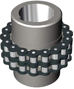
GL-type roller chain coupling AUTOCAD renderings (GB6069-2002 instead of GB6069-86) Features: The chain coupling uses a common chain and meshes with two parallel sprockets with the same number of teeth at the same time. Chain couplings of different structural types The main difference between the shafts is the use of different chains, the common ones are double-row roller chain couplings, single-row roller chain couplings, toothed chain couplings, nylon chain couplings, etc.The performance of double-row roller chain couplings is better than other structural types of couplings, and is widely used at home and abroad. my country has also formulated it as a national standard.
The basic parameters and main dimensions of GL roller chain coupling (GB/T 6069-2002) (unit: mm)
| model |
Nominal torque Tn N·m |
Permissible speed [n] r/min |
Diameter of shaft hole | Diameter of shaft hole | Chain number |
Pitch P |
Number of teeth Z |
D | S |
质量 Kg |
Moment of inertia I /kg·m2 |
||
| Y | J1 | ||||||||||||
| Without cover | Install the cover | d1,d2 | L, L1 | ||||||||||
| GL1 | 40 | 1400 | 4500 | 16-20 | 42-52 | 38 | 0.6B | 9.525 | 14 | 51.06 | 4.9 | 0.4 | 0.00010 |
| GL2 | 63 | 1250 | 4500 | 19-24 | 42-52 | 38 | 0.6B | 9.525 | 16 | 57.08 | 4.9 | 0.7 | 0.00020 |
| GL3 | 100 | 1000 | 4000 | 20-25 | 52-62 | 38-44 | 0.8B | 12.70 | 14 | 68.88 | 6.7 | 1.1 | 0.00038 |
| GL4 | 160 | 1000 | 4000 | 24-32 | 52-82 | 44-60 | 0.8B | 12.70 | 16 | 76.91 | 6.7 | 1.8 | 0.00086 |
| GL5 | 250 | 800 | 3150 | 28-40 | 62-112 | 60-84 | 10A | 15.875 | 16 | 94.46 | 9.2 | 3.2 | 0.0025 |
| GL6 | 400 | 630 | 2500 | 32-50 | 82-112 | 60-84 | 10A | 15.875 | 20 | 116.57 | 9.2 | 5.0 | 0.0058 |
| GL7 | 630 | 630 | 2500 | 40-60 | 112-142 | 84-107 | 12A | 19.05 | 18 | 127.78 | 10.9 | 7.4 | 0.012 |
| GL8 | 1000 | 500 | 2240 | 45-70 | 112-142 | 84-107 | 16A | 25.40 | 16 | 154.33 | 14.3 | 11.1 | 0.025 |
| GL9 | 1600 | 400 | 2000 | 50-80 | 112-172 | 84-132 | 16A | 25.40 | 20 | 186.50 | 143. | 20.0 | 0.061 |
| GL10 | 2500 | 315 | 1600 | 60-90 | 142-172 | 107-132 | 20A | 31.75 | 18 | 213.02 | 17.8 | 26.1 | 0.079 |
| GL11 | 4000 | 250 | 1500 | 75-100 | 142-212 | 107-167 | 24A | 38.10 | 16 | 231.49 | 21.5 | 39.2 | 0.188 |
| GL12 | 6300 | 250 | 1250 | 85-120 | 172-212 | 132-167 | 28A | 44.45 | 16 | 270.08 | 24.9 | 59.4 | 0.380 |
| GL13 | 10000 | 200 | 1120 | 100-140 | 212-252 | 167-202 | 32A | 50.80 | 18 | 340.80 | 28.6 | 86.5 | 0.869 |
| GL14 | 16000 | 200 | 1000 | 120-160 | 212-302 | 167-242 | 32A | 50.80 | 22 | 405.22 | 28.6 | 150.8 | 2.06 |
| GL15 | 25000 | 200 | 900 | 140-190 | 252-352 | 202-282 | 40A | 63.50 | 20 | 466.25 | 35.6 | 234.4 | 4.37 |
Note: 1. When there is a cover, add "F" after the model number, such as GL5 type coupling. When there is a cover, change it to GL5F. 2. The coupling mass and moment of inertia in the table are approximate values
- LM type basic plum blossom elastic coupling LT type (formerly TL type) elastic sleeve pin coupling LMD (formerly MLZ) type single flange plum-shaped bullet XL type star elastic coupling T type plum blossom hexagonal water pump counter wheel pad
-
Popular products
- KC series chain coupling GL type roller chain coupling AUTOCAD effect
-
Related Products
-
related news