-
Star flexible coupling
-
Plum-shaped elastic coupling
-
Slider coupling
-
Diaphragm coupling
-
Elastic sleeve pin coupling
-
Elastic pin coupling
-
Elastic pin gear coupling
-
Drum gear coupling
-
Rigid coupling
-
Tyre coupling
-
Universal coupling
-
Water pump coupling
-
Roller chain coupling
-
Reducer bracket
-
Blender
-
Stuffing box
-
Expansion sleeve
-
Various coupling accessories
-
Product Navigation
- LM type basic plum blossom elastic coupling
- LT type (formerly TL type) elastic sleeve pin coupling
- LMD (formerly MLZ) type single flange plum-shaped bullet
- XL type star elastic coupling
- Ever-Power Factory Slider Coupling
- Ever-Power explains the elastic pin teeth for you
- Operation and structure of star coupling
- The editor will introduce you to each model
- The coupling is divided into lubricated and non-lubricated
- What to consider when buying a coupling
-
更新 更新
-
Product display Coupling > Product center > Expansion sleeve >
Z7A type locking coupling plate

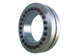
The basic size of Z7A type locking coupling disc (produced according to JB/T 7934-1999)
Selection and installation sequence of various shrink disks
1.
When the shaft diameter is the first requirement of the design, select the lock disk in this product catalog according to the shaft diameter (dw) selected by the design, and check whether the corresponding maximum transmission torque (Mt) can meet the torque requirement.
Conversely, if torque is the first requirement, select the required torque (Mt) from the catalog according to the appropriate model, and then find the corresponding shaft diameter (dw).
II
Check the size and strength of the shaft and sleeve according to the selected shrink disk.
The outer diameter (d) of the sleeve or hollow shaft is consistent with the inner diameter of the locking disc.The minimum cross section of the shaft sleeve can safely transmit the specified torque.
III
The rated torque Mt and rated axial load Pax listed in the catalogue are listed in accordance with the maximum value that can be transmitted by the shrink disk without a safety factor. The starting and impact load should be considered when checking.
IV
The relationship between the transmission torque value (Mt) and the shaft diameter (dw) is a linear function relationship. All the rated torques corresponding to the shaft diameter are not listed in the model catalog table, but a certain shaft diameter can be obtained by interpolation. The torque.
V
for example:
To connect a 103mm shaft, a shrink disk must be installed, and its maximum transmission torque is determined to be 12400Nm. Select the shrink disk model and specifications.
The first step: the diameter of the shaft is close to 100mm. ,
第二步:在标准系列71型规格表中,找出轴径100mm对应锁紧盘型号为SD140-71,用插放法计算出 103mm轴可传递最大扭矩为17600Nm与20100Nm间的19100Nm。
The third step: verify the size of the determined locking disk and design it on the drawing.
Step XNUMX: Find out the required processing tolerances and applicable matching methods.
That is: the tolerance of the shaft and the inner hole of the shaft sleeve is H7/h6, and the outer diameter of the shaft sleeve is f7.
Step 140: Choose the shrink disk, and order according to the following model: the shrink disk SD71-XNUMX.
Things to note
In order to ensure the torque and axial load values listed in the catalog table, it is very important to specify that the locking screw is tightened according to the specified tightening torque Ma when designing the drawing.
Since the shrink disk and the screw are only subjected to static force, there is no need to worry about the screw loosening.
Installation and removal
The shrink disk is ready for installation before leaving the factory, so there is no need to disassemble it before the first installation;
1. Remove the middle partition of the outer ring that plays a protective role during transportation.
2. Take any three locking screws to form an isosceles triangle, and tighten them lightly until the inner ring can still rotate. Tightening too hard will cause plastic deformation of the inner ring.
3. Let the shrink disk slide on the sleeve, and the outer ring of the sleeve can be greased and lubricated. ,
Note: Remember to tighten the screws before installing the shaft into the sleeve.
4. Wipe off the grease in the shaft and the inner hole of the shaft sleeve.
5. Insert the shaft into the grease in the inner hole of the shaft sleeve.
6. Use the force measurement wrench to tighten all the locking screws.The tightening method is to tighten gradually in order, each time only to 1/4 of the rated torque.
It is very important to check the tightening torque Ma with a torque handle.The two locking rings must be kept equidistant.
| basic size | Socket head cap screws | Rated load |
Screw Tighten Torque MA N · m |
weight kg |
|||||||
| d | D | dn | L | H | e | d1 | n |
Axial force F1 KN |
Torque M1 KN·m |
||
| mm | |||||||||||
| 125 | 185 | 95 | 39 | 52 | 6 | M10 × 40 | 8 | 242 | 11.5 | 58 | 6 |
| 100 | 260 | 13 | |||||||||
| 105 | 276 | 14.5 | |||||||||
| 140 | 220 | 110 | 10 | 391 | 16 | 8 | |||||
| 120 | 330 | 20 | |||||||||
| 125 | 352 | 22 | |||||||||
| 155 | 245 | 130 | 12 | 385 | 25 | 10 | |||||
| 135 | 427 | 28.8 | |||||||||
| 140 | 464 | 32.5 | |||||||||
| 165 | 260 | 135 | 46 | 62 | 8 | M12 × 50 | 10 | 474 | 32 | 100 | 14 |
| 140 | 507 | 32.5 | |||||||||
| 145 | 538 | 39 | |||||||||
| 175 | 275 | 145 | 538 | 39 | 16 | ||||||
| 150 | 573 | 43 | |||||||||
| 155 | 606 | 47 | |||||||||
| 185 | 295 | 155 | 12 | 632 | 49 | 20 | |||||
| 160 | 662 | 53 | |||||||||
| 165 | 691 | 57 | |||||||||
| 195 | 315 | 165 | 56 | 72 | M12 × 55 | 15 | 800 | 66 | 27 | ||
| 170 | 835 | 71 | |||||||||
| 175 | 869 | 76 | |||||||||
| 220 | 345 | 180 | 66 | 84 | 9 | M16 × 65 | 9 | 978 | 88 | 240 | 35 |
| 190 | 1063 | 101 | |||||||||
| 200 | 1140 | 114 | |||||||||
| 240 | 370 | 200 | 12 | 1200 | 120 | 44 | |||||
| 210 | 1276 | 134 | |||||||||
| 215 | 1312 | 141 | |||||||||
| 260 | 395 | 220 | 72 | 92 | M16 × 70 | 1309 | 144 | 48 | |||
| 230 | 1384 | 159 | |||||||||
| 235 | 1421 | 167 | |||||||||
| 280 | 425 | 230 | 84 | 104 | 10 | M16 × 75 | 15 | 1478 | 170 | 60 | |
| 240 | 1583 | 190 | |||||||||
| 250 | 1680 | 210 | |||||||||
| 300 | 460 | 250 | 16 | 1704 | 213 | 75 | |||||
| 260 | 1800 | 234 | |||||||||
| 270 | 1889 | 255 | |||||||||
| 320 | 495 | 270 | 106 | 11 | M16 × 80 | 18 | 1955 | 264 | 84 | ||
| 280 | 2036 | 285 | |||||||||
| 290 | 2076 | 301 | |||||||||
| 340 | 535 | 290 | 20 | 2193 | 318 | 100 | |||||
| 300 | 2300 | 345 | |||||||||
| 305 | 2354 | 359 | |||||||||
| 360 | 555 | 300 | 100 | 122 | M20 × 90 | 15 | 2547 | 382 | 470 | 125 | |
| 310 | 2645 | 410 | |||||||||
| 320 | 2738 | 438 | |||||||||
| 390 | 595 | 330 | 112 | 136 | 12 | M20 × 100 | 18 | 3091 | 510 | 156 | |
| 340 | 3194 | 543 | |||||||||
| 350 | 3291 | 576 | |||||||||
| 420 | 630 | 350 | 120 | 144 | 20 | 3371 | 590 | 185 | |||
| 360 | 3500 | 630 | |||||||||
| 370 | 3620 | 670 | |||||||||
| 460 | 685 | 390 | 132 | 158 | 13 | M20 × 110 | 24 | 3949 | 770 | 470 | 235 |
| 400 | 4300 | 860 | |||||||||
| 410 | 4634 | 950 | |||||||||
| 500 | 750 | 420 | 152 | 178 | M20 × 120 | 30 | 4881 | 1025 | 320 | ||
| 430 | 5233 | 1125 | |||||||||
| 440 | 5568 | 1225 | |||||||||
The Z7 expansion sleeve is a keyless coupling device between the shaft and the sleeve. This device can apply a clamping force to the sleeve from the outside to form a mechanical compression fit between the shaft and the sleeve, thereby transmitting torque and expanding the sleeve. It does not transmit any torque or load.
- LM type basic plum blossom elastic coupling LT type (formerly TL type) elastic sleeve pin coupling LMD (formerly MLZ) type single flange plum-shaped bullet XL type star elastic coupling T type plum blossom hexagonal water pump counter wheel pad
-
Popular products
- Z13 type expansion joint sleeve Z19A type expansion joint sleeve Z7B type expansion joint sleeve Z12A type expansion joint sleeve Z9 type expansion joint sleeve
-
Related Products
-
related news